


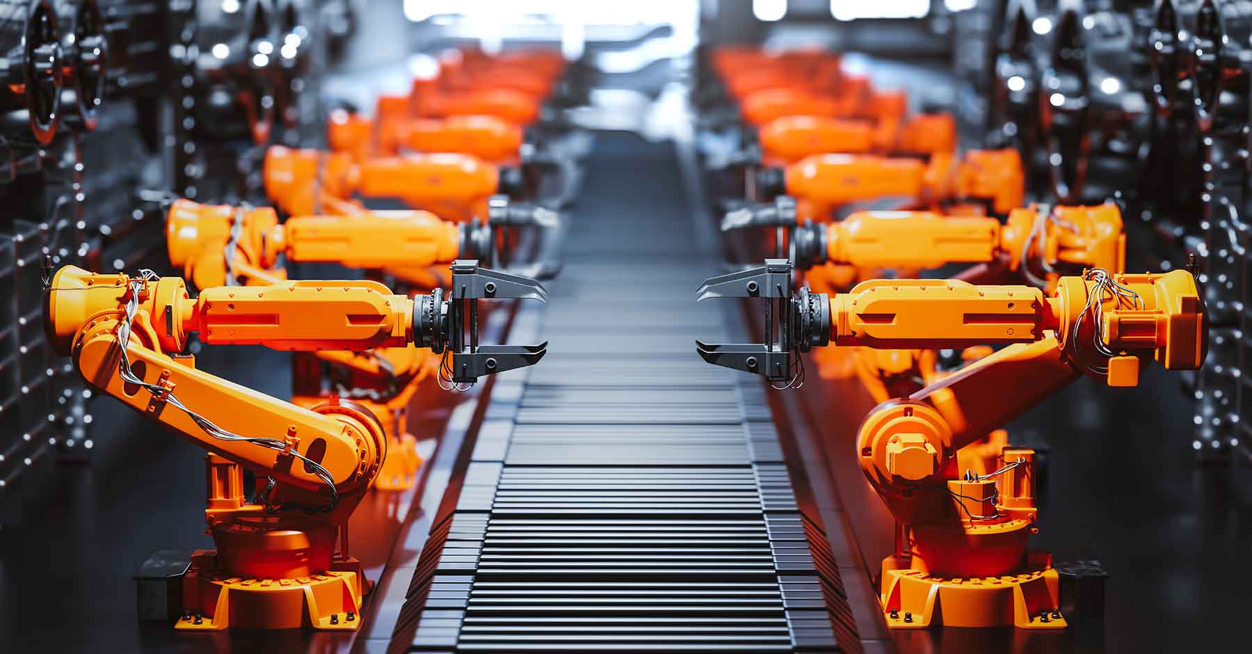
Linear motion bearings are critical components used in applications that require precise, reliable linear movement along a straight path. These specialized bearings are designed to reduce friction while supporting dynamic or static loads, enabling efficient and controlled motion in mechanical systems. Typically utilized in industries such as manufacturing, automation, robotics, and medical devices, linear motion bearings are integral to enhancing machine performance and operational accuracy.
This article will provide a comprehensive overview of linear motion bearings, including their fundamental working principles, various types, key advantages, and real-world applications. By exploring the underlying technologies and design considerations, readers will gain a deeper understanding of how these components contribute to the performance of modern machinery. Whether you are a practitioner in mechanical engineering or simply interested in precision technology, this guide will equip you with valuable insights into the world of linear motion bearings.
What Is a Linear Motion Bearing and How Does It Work?
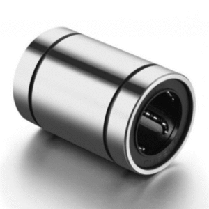
A linear motion bearing is a precision-engineered mechanical component designed to facilitate smooth, low-friction, and accurate linear movement along a straight path. It operates by employing rolling elements, such as balls or rollers, that minimize resistance between the moving surfaces. These bearings are typically housed in a specialized carriage or base, which moves along a guide rail or track to ensure precise alignment and stability. The fundamental principle behind their operation is the conversion of sliding motion into rolling motion, significantly reducing wear and energy loss while enhancing efficiency and reliability. Linear motion bearings are integral to various mechanical systems, where they enable precise positioning and repeatable motion under high loads or demanding conditions. If you are looking for more information about linear motion bearing go here right away
Exploring the Basics of Bearing Technology
Types and Applications of Bearings
Bearings are mechanical components designed to reduce friction between moving parts and support loads, which are critical for smooth and efficient operation in machinery. There are numerous types of bearings, each optimized for specific applications and load demands.
- Ball Bearings – These are the most common type and are suited for applications requiring low friction and smooth rotation. They handle both radial and axial loads and are widely used in electric motors, fans, and hard drives.
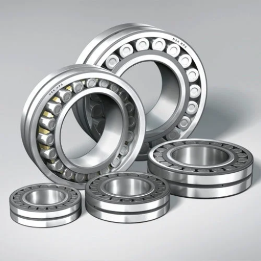
- Roller Bearings – Built for heavier loads, roller bearings distribute the load over a larger surface area using cylindrical, tapered, or spherical rollers. Typical applications include conveyor belts, gearboxes, and heavy equipment.
- Needle Bearings – These bearings utilize long and thin rollers, making them ideal for applications with limited space and high radial load requirements, such as automotive components and portable tools.
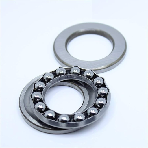
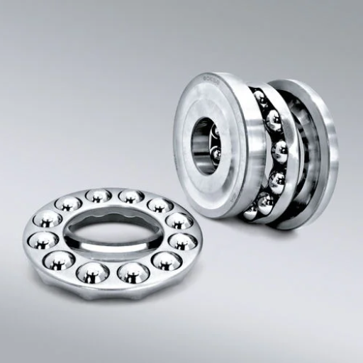
- Thrust Bearings – These are designed specifically to handle axial loads and are used in systems such as automotive transmissions and rotating platforms.
- Linear Bearings – Used in applications requiring straight-line motion, such as CNC machines and 3D printers, these allow for high precision and minimal friction along a guide rail or track.
Each type of bearing has distinct characteristics that make it suitable for specific environmental and operational conditions, such as load type, rotation speed, temperature, and lubrication requirements. Selecting the proper bearing for an application involves balancing these factors to ensure longevity, reliability, and performance.
How Do Linear Bearings Facilitate Smooth Motion?
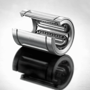
Linear bearings facilitate smooth motion by minimizing friction between moving parts, enabling precision and efficiency in mechanical systems. They achieve this through the use of rolling elements, such as balls or rollers, that reduce the amount of direct surface contact between the bearing and the guide rail. This design not only decreases wear but also ensures highly accurate and repeatable motion.
Key technical parameters to consider while evaluating linear bearings include:
- Load Capacity (Static and Dynamic): The maximum load a bearing can support without performance degradation, typically measured in Newtons (N).
- Coefficient of Friction: Typically as low as 0.001–0.005 for ball-based linear bearings, contributing to smooth operation.
- Operating Speed: Linear bearings can support speeds up to 2–5 m/s depending on the design and lubrication type.
- Operating Temperature Range: Commonly between -20°C to 100°C but may extend higher for specialized materials.
- Precision: Tolerance levels often range between ±2 to ±10 microns, depending on the application.
Proper installation, alignment, and lubrication further enhance the performance of linear bearings, ensuring consistent, smooth motion in applications such as CNC machines, automation systems, and robotics.
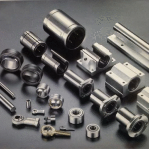
Key Components of a Linear Motion Bearing
A linear motion bearing consists of several critical components that facilitate precise and smooth linear movement:
- Bearing Housing: This outer shell holds and protects the internal elements of the bearing, maintaining proper alignment. It is often constructed from durable materials such as steel or aluminum to withstand operational stresses.
- Rolling Elements: These are typically balls or rollers, depending on the bearing type. They are responsible for reducing friction and ensuring smooth motion along a guide or shaft.
- Raceways or Track: The surfaces on which the rolling elements move are carefully engineered to provide low-friction performance and high load capacity.
- Lubrication System: Proper lubrication, whether it be grease or oil, minimizes wear, reduces friction, and helps dissipate heat, prolonging the life of the bearing.
- Seals or Shields: These prevent contaminants such as dust, dirt, or moisture from entering the bearing, ensuring optimal operation and reducing maintenance needs.
Each of these components must work cohesively to deliver the high precision and efficiency required in demanding industrial applications. Their design and material choices are tailored to suit specific operational needs, such as load capacity, speed, and environmental conditions.
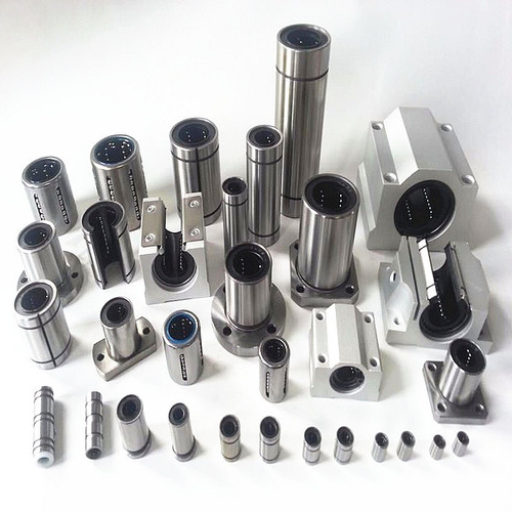
Types of Linear Bearings: Which One Is Right for Your Application?

Selecting the appropriate type of linear bearing depends on several critical factors, including the application’s load requirements, operating environment, motion precision, speed, and maintenance constraints. Here are the main types:
- Ball Bushing Bearings
Ideal for applications requiring low friction, high precision, and smooth motion. Commonly used in automation, robotics, and CNC machines.
- Roller Linear Bearings
Suited for heavy load applications due to their high load capacity and durability. These are frequently employed in industrial machinery and material handling systems.
- Plain Linear Bearings
Best for harsh environments as they operate without ball bearings, making them resistant to contamination from dirt or debris. Found in woodworking tools and packaging machinery.
- Profile Rail Bearings (Linear Guides)
Designed for precise motion under high load conditions, these are used in industries that demand accuracy, such as semiconductor manufacturing and medical devices.
- Crossed Roller Bearings
Offer exceptional rigidity and accuracy, commonly used in optical instruments and precision measuring equipment.
By evaluating the specific operational parameters and environmental conditions, users can determine which linear bearing type will provide optimal performance and longevity for their application.
Comparing Ball Bearings and Roller Bearings
When comparing ball bearings and roller bearings, the choice largely depends on the application and load conditions. Ball bearings are designed to handle lighter, high-speed applications due to their point contact between the balls and raceways, which minimizes friction. On the other hand, roller bearings excel in applications with heavier loads and higher radial forces because their line contact provides superior load distribution. While ball bearings are more versatile and typically used in applications requiring smooth, low-friction movement, roller bearings offer greater durability and stability under high stress. The specific operational requirements should always guide the selection process.
Understanding Plain Bearings and Their Uses
Plain bearings, also known as bushings or journal bearings, are simple mechanical components designed to provide a sliding motion between two surfaces, often in rotary or linear applications. Unlike ball or roller bearings, plain bearings do not contain rolling elements, which makes them compact, cost-effective, and reliable in many use cases. They are particularly suited for applications with moderate loads and low to medium speeds, where minimizing noise and vibration is crucial.
When using plain bearings, certain technical parameters should be considered to ensure optimal performance. These include:
- Load Capacity: Typically ranges from 50 to 150 MPa, depending on the material and design.
- PV Rating (Pressure-Velocity): A critical factor involving the product of pressure (MPa) and sliding velocity (m/s), often staying within 0.25 to 1.0 MPa·m/s for standard applications.
- Operating Temperature: Plain bearings can generally operate between -200°F to 600°F (-129°C to 315°C), depending on the lubricant and material used.
- Coefficient of Friction: Typically between 0.02 and 0.2, influenced by surface finish, lubrication, and material pairing.
Plain bearings are commonly made from materials such as bronze, composites, or polymer-based compounds, often incorporating lubricants to reduce wear and extend lifespan. Their uses span industries, including automotive, aerospace, and industrial machinery, where simplicity, efficiency, and low maintenance are prioritized.
When to Choose a Ball Spline or Linear Guide
The decision to use a ball spline or linear guide hinges on specific application requirements, such as load distribution, motion precision, and system constraints.
Ball Spline:
A ball spline is ideal for applications requiring simultaneous linear and rotational motion. It provides smooth torque transfer and accommodates angular misalignment to some degree. Key technical parameters to consider include torque capacity, linear load capacity, and accuracy grade. For example, torque values can range from 5 Nm to over 1,000 Nm depending on spline size and structure. Common use cases include robotic arms, machine tool spindles, and high-dexterity automation systems. Ball splines are particularly advantageous in systems where torsional rigidity and compact design are critical.
Linear Guide:
Linear guides are optimized for applications focusing exclusively on linear motion with high load-bearing capability and precision. They ensure stable motion under heavy loads due to their wide contact area between the rail and block. Key parameters include dynamic load capacity (often exceeding 20 kN for industrial applications), static load rating, permissible speed (commonly up to 5 m/s), and positional accuracy (down to micrometer levels for fine-tuned models). Linear guides are used in CNC machines, 3D printers, and high-precision assembly machinery where exact linear alignment is paramount.
Comparison and Selection:
- Motion Type:
-
-
- Choose a ball spline for combined linear and rotational needs.
- Opt for a linear guide for pure linear motion.
-
- Load and Speed:
-
-
- Ball splines handle moderate linear loads with rotational motion, while linear guides excel under higher static and dynamic loads with quicker speeds.
-
- Precision:
-
-
- Linear guides generally provide higher positional accuracy than ball splines.
-
- Environment:
-
-
- Ball splines perform well in flexible motion systems, whereas linear guides thrive in environments requiring rigid alignment and stability under load.
-
Selecting between the two should involve a thorough analysis of operational demands, system design, and desired performance to ensure maximum efficiency and reliability.
How to Maximize the Service Life of Your Linear Bearings
To maximize the service life of your linear bearings, it is critical to implement proper maintenance and operational practices. Start by ensuring regular lubrication using the manufacturer-recommended grease or oil to reduce friction and wear. Periodic cleaning is also essential to remove debris or contaminants that could damage the bearing surfaces. Aligning the bearing correctly with the load path minimizes uneven stress distribution, which can lead to premature failure. Additionally, avoid overloading the bearings by adhering to specified load and speed ratings, as exceeding these limits can cause irreversible damage. Finally, routinely inspect the bearings for signs of wear, corrosion, or misalignment, allowing for prompt replacement or adjustment if necessary.
Importance of Proper Lubrication
Proper lubrication is essential to ensure the efficient operation and longevity of bearings. Lubricants reduce friction between moving parts, minimizing wear and preventing excessive heat buildup that could degrade bearing performance. An appropriate selection of lubricant type—be it grease or oil based on operating conditions such as speed, load, and temperature—is critical to maintaining optimal bearing function. Insufficient lubrication can result in surface damage, contamination ingress, and oxidative degradation, while over-lubrication can increase resistance, leading to energy loss and overheating. Regular maintenance schedules should include monitoring lubricant condition and replenishment intervals to ensure maximum efficiency and reliability of the system.
Regular Maintenance and Inspection
To address your questions concisely, I would emphasize that regular maintenance and inspection involve adhering to a structured schedule to evaluate component health and ensure system reliability. I prioritize checking the condition of lubrication under specific working conditions, as proper lubrication directly impacts bearing efficiency and longevity. Additionally, I assess for signs of wear, contamination, or misalignment during each inspection, as these factors could lead to premature failure. Using data-driven insights from top resources, I ensure corrective actions are implemented promptly, such as replenishing or adjusting lubricant levels and replacing damaged components, to maintain seamless operation.
Identifying and Preventing Common Failures
When identifying and preventing common failures, I rely on a systematic approach supported by industry best practices. I start by analyzing key failure modes such as fatigue, corrosion, and overheating, which are frequently cited as leading causes of equipment malfunction. By conducting regular condition monitoring—utilizing advanced tools like vibration analysis, thermal imaging, and lubrication testing—I can detect anomalies early. Additionally, I prioritize preventive actions, including implementing robust maintenance schedules, ensuring the use of high-quality materials compatible with operational demands, and maintaining rigorous environmental controls to mitigate external stressors. These measures significantly reduce downtime and enhance system reliability.
Designing with Linear Motion Systems: Tips and Tools
When designing with linear motion systems, several critical factors must be evaluated to ensure optimal performance and system longevity. First, accurately determine the load requirements, including weight, size, and orientation, as these directly influence the selection of actuators, guides, and drive mechanisms. Second, consider the desired speed and precision, as these parameters will determine the suitability of lead screws, ball screws, or belt-driven systems. Third, evaluate the operating environment for conditions like temperature, contaminants, and humidity to select appropriate materials, coatings, and sealing options. Additionally, integrate advanced tools such as CAD software for precise modeling and simulation, and leverage control systems for feedback and automation capabilities. Implementing meticulous alignment and maintenance procedures further ensures the system’s reliability and extended operational life.
Using CAD for Precision Design
Computer-Aided Design (CAD) tools play a pivotal role in ensuring precision and efficiency in modern design workflows. By utilizing CAD systems, you can accurately model complex geometries, perform stress analyses, and simulate dynamic interactions, all while reducing prototyping costs and improving production timelines. Key technical parameters to monitor include:
- Dimensional Accuracy: Ensure tolerances up to ±0.01 mm for high-precision components.
- Material Properties: Input accurate material characteristics (e.g., Young’s Modulus, Poisson’s Ratio) for realistic simulation results.
- Load Conditions: Define static and dynamic forces, with a focus on magnitude, direction, and application points.
- Thermal Analysis: Incorporate thermal constraints by setting operating and ambient temperature ranges (e.g., -20°C to 100°C).
- Geometric Constraints: Apply constraints like symmetry, parallelism, or perpendicularity to maintain design intent.
- Simulation Settings: Optimize meshing resolution and boundary conditions to balance accuracy and computational efficiency.
By refining these parameters through iterative adjustments, CAD enables designers to eliminate ambiguities, enhance structural integrity, and achieve optimal functionality in both prototyping and final production phases.
Calculating Load Capacity and Performance
To accurately calculate load capacity and assess performance, a detailed understanding of material properties, structural geometry, and applied forces is essential. The process typically involves the following steps:
- Material Analysis: Identify the material’s yield strength, tensile strength, and elastic modulus, as these properties directly influence load-bearing capacity.
- Force and Load Calculations: Determine the types of forces acting on the structure—such as axial, shear, bending, or torsional forces—and apply equations like \( \sigma = \frac{F}{A} \) (stress = force/area) to assess individual stress components.
- Safety Factor Implementation: Apply a suitable safety factor to account for uncertainties in material properties and operating conditions, ensuring the structure remains operational under maximum predicted loads.
- Finite Element Analysis (FEA): Perform numerical simulations to evaluate stress distribution, deformation, and failure points within the structure. FEA tools allow for precise modeling of complex geometries and real-world loading scenarios.
- Performance Validation: Conduct experimental testing to compare theoretical predictions with actual performance metrics, refining parameters as needed.
By integrating these approaches, engineers can ensure optimal structural performance and reliability under designated operational conditions, adhering to industry standards and safety regulations.
Integrating Linear Shafts and Slides into Your Project
When integrating linear shafts and slides into my project, I start by determining the specific application requirements, such as load capacity, stroke length, and operating environment. I then select shafts and slides made from materials suitable for my project’s conditions, like stainless steel for high corrosion resistance or aluminum for lightweight applications. Next, I ensure precise alignment of components to minimize friction and wear. I also consider using high-quality bearings that match the loads and speeds the system will experience. Finally, I refer to manufacturers’ installation guides and specifications to ensure compliance with design standards, optimizing performance and reliability in the final implementation.
How to Choose the Right Linear Guide or Slide for Your Needs

When selecting the appropriate linear guide or slide for your application, begin by assessing the load capacity requirements, including both static and dynamic loads, to ensure the chosen guide can handle the operational demands. Next, evaluate the precision and rigidity needed, as applications requiring high accuracy may benefit from preloaded systems that reduce backlash. Consider environmental factors such as temperature, humidity, or potential exposure to contaminants, as these will influence the choice of materials and protective coatings. Additionally, examine the speed and acceleration demands, ensuring the guide system’s design and lubrication options can sustain consistent performance. Finally, compare the dimensional constraints and mounting configurations of the guide or slide to confirm compatibility with your existing system. By addressing these criteria systematically, you can select a solution that maximizes efficiency, durability, and operational reliability.
Factors to Consider: Load Capacity and Speed
When considering load capacity and speed for guide systems, I prioritize several critical parameters to ensure optimal performance. For load capacity, it is essential to assess both the static and dynamic load ratings, typically provided in Newtons (N). A high static load rating ensures the system can sustain heavy loads without deformation, while the dynamic capacity indicates its ability to handle fluctuating loads during operation. For speed, the maximum allowable speed, usually expressed in meters per second (m/s), should align with the application’s requirements, taking into account the acceleration and deceleration rates. Additionally, factors like permissible duty cycle, wear resistance, and thermal performance under continuous operation should also be evaluated to match the high-speed demands reliably.
Material Choices: Anodized Aluminum and More
Anodized aluminum is frequently selected due to its high strength-to-weight ratio, corrosion resistance, and ability to perform under variable environmental conditions. The anodizing process enhances the natural oxide layer, increasing surface hardness (typically 60-70 HRC) and wear resistance. This material also exhibits excellent thermal conductivity, often around 235 W/m·K, making it suitable for applications requiring efficient heat dissipation.
Additionally, stainless steel and titanium are notable alternatives depending on specific application requirements. Stainless steel offers superior rigidity and resistance to extreme temperatures, with a tensile strength range between 490-620 MPa for common grades like 304 and 316. Titanium, while more expensive, is valued for its exceptional strength-to-weight ratio and biocompatibility, often used in aerospace and medical industries. Common grades, such as Grade 5 (Ti-6Al-4V), deliver a tensile strength of 950 MPa while remaining relatively lightweight.
While picking materials to work with, parameters such as thermal expansion coefficients, loads, and the environment should be considered. For example, the thermal expansion coefficient for aluminum is 23.1 µm/m·K whereas, for stainless steel, depending on the alloy, it is on average 16 µm/m·K. The amalgamation of operational parameters and technical requirements ensures that the performance of the chosen material will be optimal for the intended application.
Understanding Self-Lubricating Options
Self-lubricating materials are engineered to reduce friction and wear without requiring additional lubrication during operation. These materials integrate lubricants directly into their structure, ensuring reliability in applications where periodic maintenance is impractical or where lubricant contamination is a concern.
Key self-lubricating materials include:
- Polytetrafluoroethylene (PTFE): Known for its low friction coefficient (approximately 0.04) and chemical resistance, PTFE is often used in applications that demand high performance at moderate loads and temperatures up to 260°C.
- Graphite-Based Composites: Graphite exhibits excellent lubrication properties due to its layered crystalline structure. Common in high-temperature applications, it handles loads up to 10,000 psi and temperatures exceeding 500°C, making it suitable for extreme environments.
- Oil-Impregnated Bronze: Featuring a porous composition filled with lubricating oil, these materials provide consistent lubrication over time. They are ideal for moderate-speed applications with loads typically up to 3,000 psi and temperatures between -10°C and 250°C.
- Molybdenum Disulfide (MoS₂): A popular solid lubricant, MoS₂ has a low friction coefficient (0.03 to 0.1) and is well-suited for high-pressure, vacuum, or space applications due to its stability at high temperatures (up to 350°C).
Each self-lubricating material has specific properties tailored to its use case, and selecting the appropriate option depends on operating conditions such as load, temperature, speed, and environmental exposure. Proper evaluation of these technical parameters ensures longevity and reliable performance in critical applications.
Reference Sources
- Wikipedia: Linear-motion bearing – A general overview of linear motion bearings, their types, and applications.
- IQS Directory: Linear Bearings – Types, Production, and Designs – Detailed insights into the types and designs of linear bearings.
- Zaber: Types of Bearings in Linear Motion Systems – A guide to the purpose and functionality of linear bearings.
- McMaster-Carr: Linear Motion Guides – A comprehensive catalog of linear motion guides and bearings.
- Rollon: Linear Guides for High Loads – Information on high-performance linear guides with ball and roller bearings.
Frequently Asked Questions (FAQs)
Q: What is a linear motion bearing?
A: A linear motion bearing is a type of bearing designed to provide free motion in one direction. These bearings are used to support and guide moving parts in machinery, allowing for smooth and precise movement along a linear path.
Q: How does a linear ball bearing work?
A: A linear ball bearing uses steel balls to provide low-friction linear movement along a cylindrical shaft. The balls recirculate within the bearing, reducing friction and allowing for higher speeds and greater precision in the linear motion.
Q: What are the benefits of using a linear ball bearing?
A: Linear ball bearings offer several benefits, including less friction, smooth and precise movement, higher speeds, and the ability to handle higher loads. They also require less maintenance compared to other types of bearings.
Q: What is a pillow block linear bearing?
A: A pillow block linear bearing is a type of bearing that is mounted in a housing, typically used to support a rotating shaft. It provides a secure and stable mounting for the bearing, allowing for efficient linear motion.
Q: What is the difference between open pillow block and closed pillow block bearings?
A: Open pillow block bearings have an opening that allows for easy installation and removal of the shaft, while closed pillow block bearings are fully enclosed and offer better protection from contaminants and debris.
Q: What is a linear slide and how is it used?
A: A linear slide is a mechanical component that enables linear motion of parts along a guideway. They are used in applications like industrial machinery and robotics where smooth, controlled movement is necessary.
Q: What are linear sleeve bearings and how do they function?
A: Linear sleeve bearings use a sleeve to facilitate linear motion along a shaft. They are maintenance-free and offer a simple solution for applications requiring less friction and load capacity.
Q: How do flange bearings differ from other linear bearings?
A: Flange bearings have a round flange that allows them to be easily mounted to a surface. They are commonly used when precise alignment and positioning are crucial for the application.
Q: What role does the outer ring play in a linear motion bearing?
A: The outer ring of a linear motion bearing provides structural support and houses the steel balls or other rolling elements. It helps distribute loads evenly and ensures smooth operation.
Q: When should maintenance-free linear bearings be used?
A: Maintenance-free linear bearings are ideal for applications where regular maintenance is challenging or not possible. They are designed to operate without the need for lubrication, making them suitable for environments where cleanliness is essential.


