


It is said that great things come in small packages, and this holds for the world of machinery. If used properly, even the smallest of components, such as bearings in a mechanical system, can go a long way. As an engineer, or even as a new mechanical maintenance hobbyist, knowing how to measure the bearing size is critical, for optimal performance and lifespan of your machine. This is a DIY task you do not want to take lightly, as it can cost you efficiency as well as damage and repairs. This guide aims to assist you in becoming proficient in the trade of size determination with the help of detailed illustrations supplemented with size charts throughout the guides.
What Factors Determine the Proper Bearing Size?

There are several factors to take into consideration when measuring bearing size which include:
Load Demand – Consider the load type, while fused with proportionality, will be—a radial, axial or combined bearing.
Rotation Speed – Verify whether the bearing can withstand the system’s rotational pace without performance detriment.
Dimensions of the Shaft and Housing – Select the bearing that corresponds with the dimensions of the shaft and housing for optimal fit and function.
Operating Conditions – Evaluate whether the application will be subject to contaminants, moisture, or other conditions that could affect the choice of dimensions.
Considering these aspects allows for selecting a bearing size that provides the best performance and longevity.
Understanding Bearing Types and Their Size Specifications
Bearings are classified into varying types and dimensions to suit different applications. The following is a summary of popular bearing types along with their standard dimensions:
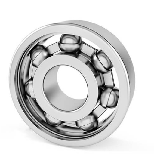
- Ball Bearings
These bearings are multifunctional in that they can accept both radial and axial loads. Commonly found in machinery such as electric motors, HVAC units, and automobiles. Their inner diameter ranges between 3mm and over 100mm, and they are manufactured with specific tolerances for high operational speeds and minimum friction.
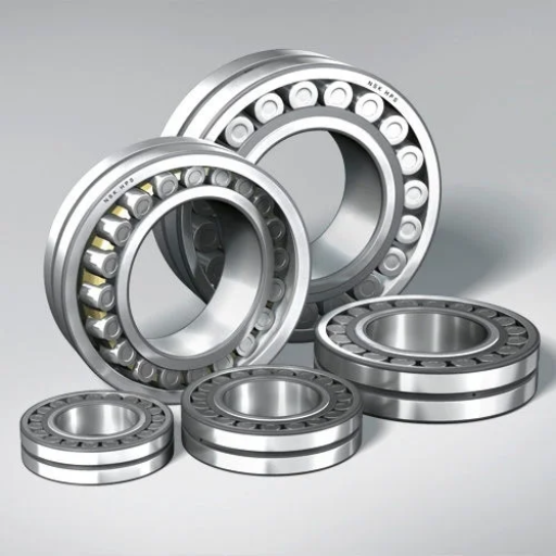
- Roller Bearings
These compensate for the balls used in ball bearings with cylindrical tapered or spherical rollers in order to enable the distribution of loads over a wider surface area. Their design makes them suitable for use in more heavy-duty applications such as conveyor systems or gearboxes. The following are common ranges of dimensions based on the type of roller used:
- Cylindrical Roller Bearings: Inner diameters can range from 5mm to 300mm.
- Tapered Roller Bearings: Sizes can go up to 450mm in large industrial applications.
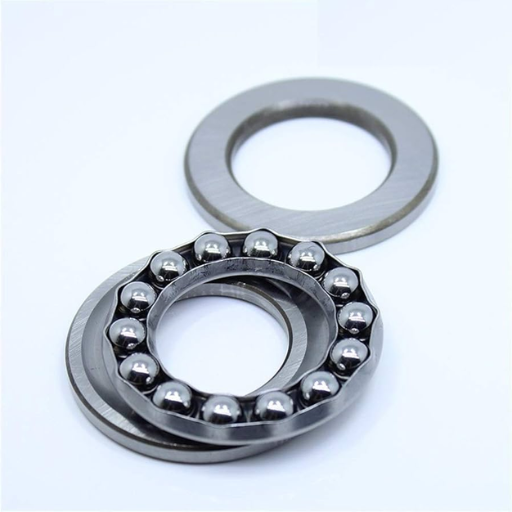
- Thrust Bearings
Contain features that allow them to primarily support axial loads parallel to the shaft which find their applications in automotive transmissions and rotating shafts. Thrust ball bearings have a diameter of 10-300mm while industrial thrust roller bearings exceed these limits for specialized machines.
- Needle Bearings
This type of bearing contains long and thin rollers that improve the loading bearing capacity while reducing the bearing’s axial cross-section. Found in automotive parts such as universal joints, needle bearings usually have diameters ranging from 3mm to approximately 200mm.
- Spherical Bearings
These bearings are used in a lot of agricultural and mining equipment as they can self-align which works well in cases with shaft misalignment. Their sizes depend on the model as well as the load requirements, meaning some can vary from 20mm to over 400mm.
- Hybrid and Ceramic Bearings
In conditions of high speeds and when the temperature is critical hybrid and ceramic bearings are often chosen. These bearings are typically the same as ball or roller bearings but because of their material composition, they’re more complex and perform much better.
How Bore Diameter and Outer Diameter Affect Bearing Selection
When picking a bearing, the outer diameter and the bore diameter are very important criteria because they affect how well the bearing will fit and work within its application. The bore diameter dictates the shaft size that the bearing can accommodate, while the outer diameter corresponds to the housing or casing in which the bearing operates.
For example, as in robotics and small electrical motors, smaller bore and outer diameters are typically helpful for compact designs. These dimensions often range from as little as 20mm to 50mm, which is ideal. However, in the wind energy industry, construction machinery, and others that require robust equipment, larger bearings with bore diameters exceeding 200 mm and outer diameters above 400 mm are used to withstand significant loads and more demanding conditions.
Selection of these dimensions incorrectly can result in misalignment, uneven load distribution, and failure by some data. In case of fitting, manufacturers often comply with international standards like ISO 15 because it classifies the bearing dimensions into series which are optimized for performance. Also, the bearing tolerances and the bearing clearances should be checked for performance, especially when there are changes in the magnitude of the load or the speed of the rotating shaft. Engineers can select bearings that suit the application mechanically, operationally, and geometrically, where the application ensures long service life as well as efficient output in the end.
The Role of Bearing Clearance in Size Calculation
Bearing clearance is vital in the evaluation of effectiveness and the useful life of a bearing. The term clearance means the space between the rolling elements and the inner and outer raceways that constitute the parts of the bearing. This space affects friction, heat generation, and load-bearing factors of an operation.
The appropriate value of clearance allows the bearing to perform its functions without going beyond set values for activity level so that friction or support does not exceed or fall below the required limits. Not enough clearance can lead to excess friction and friction-induced heat which will accelerate premature wear or failure. Too much clearance can lead to vibration, noise, and loss of stability especially with changing loads and high rotational speeds.
The leading engineering sources state the recommended clearance is different for each type of bearing, application, and operating conditions. For instance, radial ball bearings have clearances from 0.001 mm to 0.01 mm, depending on the size and series. Misalignment or imbalance often requires tighter control of clearance in high-speed applications like precision machinery, while oversized clearances can be utilized to accommodate thermal expansion and load shifts in heavy-load applications.
The appropriate clearance selection also depends on the fit of the shaft and housing, operational temperature changes, and the method of lubrication used. Engineers use ISO 5753 and DIN 620 standards to classify the clearances CN (normal clearance), C3 (greater than normal), or C4 (greater than C3), defining the appropriate classification C3 or C4.
Optimized bearing clearance considering these parameters enhances application performance and minimizes wear, preventing expensive downtime.
How to Read and Interpret Bearing Numbers?

Bearing numbers are based on a universally accepted norm which encodes very useful details about their dimensions and features. A number is usually made up of several digits arranged in the following manner:
- Series/Type Code – The first digit or digits give the type and series of the bearing. For example, deep groove ball bearing is often represented by “6”.
- Dimensional Series Code – The next digit represents the width and height series which also controls the overall proportions of the bearing.
- Bore Size Code – The last two digits represent the bore diameter which is usually the inner diameter of the bearing. To yield the value in diameter in millimeters, multiply this value by 5 (for example, “04” means a bore diameter of 20 mm).
These aspects combined allow users to determine the exact bearing structure and dimensions for their needs. Always check the manufacturer’s description for accurate definitions.
Breaking Down the Basic Number System for Bearings
Like many other components, bearings are identified through a single identification number that usually comprises various numbers and letters which line to the different characteristics of the bearing. Here is how it works step by step:
- Prefix Letters – Prefixes, when any, denote features such as the materials used, coatings, or some design modifications done to the bearing. For example, “N” indicates the bearing has a snap ring groove while “U” signifies the bearing is specially designed for particular bespoke applications.
- Bearing Series Numbers – The dimensional size also known as the ‘proportional size,’ is marked by the series digits. These could be:
- 6000 Series – Thin and lightweight bearings fit for compact fitting.
- 6200 Series – Standard medium duty general purpose bearings.
- 6300 Series – Heavy-duty bearings with high load capacity.
- Bore Diameter Code – The numerical value of the last two digits is multiplied by 5 to get as the bearing bore diameter. This does not apply to custom sizes such as “00” for 10 mm bore, “01” for 12 mm bore, etc. Also, bearings with smaller or non-standard custom bore diameters may have designations that are different from the rest.
- Suffix Letters and Numbers – Specific features like seals, shields, clearances, or lubrication details are described by suffixes:
- “ZZ” or “2Z” means double metal shields for dust protection.”2RS” is a designation for a double rubber seal to enhance sealing against contaminants.”C3″ describes a bearing with greater internal clearance that is intended for high-temperature or high-speed operation.
Additional Data on Bearing Types and Specifications
Recent developments in the field of manufacturing have led to the specialization of bearings for various purposes across different industries. For instance:
- Deep Groove Ball Bearings are the most versatile and straightforward, commonly utilized for radial and axial load operations.
- Angular Contact Ball Bearings are best suited for high-speed operations with combined load requirements.
- Tapered Roller Bearings are most effective in situations with significant axial and radial forces for heavy-duty applications.
Always consult current product catalogs and specification sheets from bearing suppliers to check compatibility with the intended machinery or application. Knowing the specifics of the numbering systems used by manufacturers will optimize operational efficiency and improve selection significantly.
Understanding Prefix, Suffix, and Supplementary Bearing Codes
Prefix Codes
In bearing identification, the prefix code usually signifies particular design features or alterations of the bearing. Take for example “N” or “NU” which refer to types of cylindrical roller bearings. “N” means the bearing type permits axial movement of the shaft, and “NU” means that the bearing has no flanges on one of the races. Prefixes may also denote particular designs such as “QJ” for angular contact ball bearings with four contact points. It is important to know these prefixes to recognize bearings designed for specialized applications.
Suffix Codes
A set of additional descriptive codes known as suffix codes comes after the main bearing number and provides additional steps that add value or features affecting performance capabilities and features such as clearances, lubrication, and cage material. For example, the suffix “C3” defines greater than normal internal clearance which is more useful for applications with fluctuating temperature or heavy vibration. Likewise, “KL” means factory greasing with long-life grease, and “P4” has lower precision standards for general-purpose bearings but higher in deeply universally used high-speed machines such as spindle motors. These codes provide guarantees for end-users to match the capability of the bearing to the serviced conditions.
Supplementary Bearing Codes
Supplementary codes enhance the description of the option of a bearing for some specific applications. For example, “2RS” indicates a bearing that is double-sealed for dust and water, while “Z” or ZZ would mean that there are metal shields on one side or both. “VA201” is a code for bearings that may be used at elevated temperatures, that is, 150°C to 200°C. These supplementary codes make sure that bearings have additional features that aid in meeting application-specific requirements to improve the reliability and life of the equipment.
Application of Codes in Bearing Selection
With these codes and detailed documents from the manufacturers, it becomes realistic to select bearings for different applications such as industrial machines and fine measuring instruments. Most companies devote product tables or charts wherein users may find the appropriate code or its equivalent as part of active support offered through their catalogs for increased operational efficiency. Through these codes, engineers and technicians can expedite the processes of selecting the appropriate bearing thereby enhancing operational efficiency and life cycle performance.
What the Series Number Reveals About Bearing Size
The series number found in the bearing designation outlines its dimensions intricately, as it pertains to the width of the bearing, outer diameter, and the load it is designed to support. The scale and divisions of the application also determine the type of duty the bearing would fall under such as light, medium or heavy-duty.
Consider the metric bearing I’ve talked about earlier and let’s say the series “6000.” This type is most likely depicting a light-duty series. The travel of bearing “0” hints at the width or section height of the bearing’s cross-section about the outer diameter. When compared to the “6200” series bearing, the “2” indicates a medium-duty design where a larger load would be supported due to larger dimensions.
Considering the contrast of the “6400” series bearing, this puts me in the heavy-duty category used in performance requirements which subject the bearing to high loads or extreme conditions. The system of classification helps the engineers verbally communicate about the bearing dimensions and applications with regard to size and the actual context in which the specific size will be utilized.
Utilizing standard sizing charts, the combination of the series number and the bore diameter is sufficient to calculate the outer diameter and width in millimeters. For example, a “6206” bearing has a bore diameter of 30mm, an outer diameter of 62mm, and a width of 16mm. The specified dimensions provide the required geometric interoperability across different mechanical configurations and multi-dimensional load scenarios. Recognizing series numbers proves critical to swiftly selecting suitable bearings for industrial, automotive, and aerospace bearings based on function and operational requirements.
What Methods Can I Use to Measure an Existing Ball Bearing?

To accurately measure an existing ball bearing, complete the following steps:
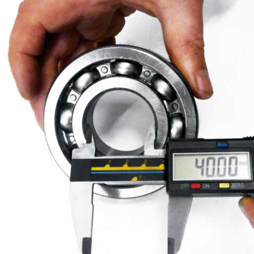
- Measure the Outer Diameter (OD): Using a caliper, measure the distance across the bearing’s outer ring at the widest point of the bearing. Please note that it must be the widest point of the bearing.
- Measure the Inner Diameter (ID): While the jaws of the caliper are set, reach for the opening of the bearing’s inner ring. The jaws need to go inside the ring whose diameter is being measured.
- Measure the Width (W): Use the caliper to measure the thickness of the bearing from its side profile, spanning from one outer edge to the other outer edge.
To identify a ball bearing, its three dimensions which are the outer diameter, inner diameter, and width must be recorded. Ensure that all measurement devices are in calibration and the bearing is clean.
Measuring Inner Diameter, Outer Diameter, and Width
Measuring the dimensions of a ball bearing accurately is critical so that it fits well with the associated machinery and functions optimally. Below is an outline of how to take each measurement properly.
- Inner Diameter (ID):
To begin, obtain a vernier caliper. Make sure that the jaws of the caliper open to the right measurement such that the fitting does not exert too much force on the bearing’s inner edge as this would lead to a faulty measurement. Standard bearings usually have inner diameters between 3 mm and 200 mm depending on the use.
- Outer Diameter (OD):
Place the external jaws of the caliper at the extreme outer edges of the bearing. It is important to note the enormous range of sizes for outer diameters from small micrometric bearings to over 800 mm on an industrial scale.
- Width (W):
With the jaws of the caliper flat on the bearing, notice how the bearing protrudes at the edge. Set the jaws such that only one face of the bearing is pressed and this is the thickness. Width for normal bearings could be in the range of 2 mm and 50 mm, however, specialized versions may exceed or have lower values.
Additional Tips for Accuracy:
- Measuring the bearing requires a clean setting void of dust because dirt can contribute to a miscalculation, Clean Bearingoms the bearing.Check These from time to Time ensure that your instruments maintain their presets.To emphasize accuracy, write down your observations in millimeters as they are the industry standard for engineering works.
Following these measuring techniques and working with the correct tools guarantees that you will size the bearing accurately for your particular installation or replacement situation.
Tips for Accurate Bearing Measurement with Common Tools
- Use a Vernier Caliper for Inner and Outer Diameter Measurements
- Ensure the caliper jaws are clean and free of debris.
- Measure the inner diameter (ID) by aligning the internal jaws with the bore of the bearing.
- Record the reading in millimeters for precision.
- For the outer diameter (OD), use the external jaws and ensure a firm, steady grip without applying excessive force.
- Measure the Width of the Bearing
- Position the bearing on a flat, level surface.
- Use the external jaws of the Vernier caliper to measure the width of the bearing while holding it perpendicular to the surface.
- Double-check the measurement to eliminate errors from misaligned tools.
- Use a Micrometer for Smaller Bearings
- Calibrate the micrometer before use to ensure accuracy.
- Gently rotate the bearing within the micrometer’s anvil and spindle to confirm consistent diameter measurements.
- Ideal for measuring small bearings or situations requiring ultra-precise results.
- Confirm Sphericity with a Dial Gauge
- Place the bearing on a rotating fixture and use the dial gauge probe to check for uniformity in spherical or cylindrical shapes.
- Note any deviations in the readings as this could indicate wear or damage.
- Measure Bearing Clearance with Feeler Gauges
- Insert the feeler gauge between the outer ring and the rolling elements. Select a gauge that fits tightly but slides smoothly.
- Compare your readings with manufacturer tolerances to determine if the bearing is suitable for use.
- Handle the Bearing with Gloves and Avoid Contamination
- Always wear clean gloves while measuring to avoid transferring dirt or grease onto the bearing.
- Contamination can impact measurements and the overall performance of the bearing in operation.
By following these tips and using appropriate tools, you can enhance the accuracy of your bearing measurements and maintain optimal performance in your mechanical systems.
How to Identify Bearing Type from Measurements
Recognizing a type of bearing requires accurate measurements and knowledge of classification. Follow these guidelines:
- Measure the Inner Diameter (ID), Outer Diameter (OD), and Width
- Make use of precision calipers and other measuring devices to record the inner diameter, outer diameter, and width of the bearing. These three geometric features must be measured to classify the bearing type.As an illustration, a common ball bearing with an inner diameter of 10mm would also have an outer diameter of 30mm and width of 9mm, suggesting that its size falls within predefined standards.
- Examine the Markings on the Bearing
- Markings consisting of the bearing series or the model number are printed or engraved on some older bearings. Such markings can be looked up in the manufacturer’s tracking systems or cataloging websites.
- Knowledge of Series and Types of Bearings
- Bearings are grouped into sets under different classifications and types such as deep groove ball bearings, spherical roller bearings or tapered roller bearings. The design, load capacity, and rotational speed of the bearing aids classify the type. For example, deep groove ball bearings support radial loads and high-speed rotation while spherical roller bearings offer resistance to misalignment and support combined loads.
- Match Measured Dimensions with Manufacturer Tables
- Referencing measurement charts can be looked up in the catalogs or digital materials of the bearing suppliers. The tables have listed scale and series which help correlate measurements with particular bearing types.
- Evaluate Application Requirements
- Bearings come in different makes and types depending on the applications they are meant for. For instance, ball bearings with angular contact are meant for high-speed spindle uses whereas cylindrical roller bearings serve cases of dominantly radial heavy loads. The context of use can further assist the identification process.
Use thorough measurements along with an understanding of bearing categories to get the right type that will fit the mechanical system. Always keep track of measurement documents and keep them safe so a reverse solution won’t be sourced in error when upgrades or replacements are intended.
How to Calculate the Right Bearing Size for Your Application?
To get the correct bearing size for your needs, follow these steps:
- Determine the Load Requirements
Get the type and amount of load that needs to be supported by the bearing, including radial and axial loads.
- Measure Shaft and Housing Dimensions
Guarantee that the shaft’s diameter and the housing bore are measured accurately so that the bearing fits properly.
- Consider Rotational Speed
Check the operational speed needed, noting that each bearing has a set speed limit which should not be exceeded.
- Evaluate Operating Conditions
Consider factors such as temperature, lubrication, and contaminant exposure.
- Use Manufacturer Data
Bearings from different manufacturers may have different design features, so check their catalogs for the measurements and requirements you have.
You greatly improve your chances of precision and reliability in identifying the correct bearing size for your needs by utilizing the steps above.
Load Calculations and Their Impact on Bearing Size Selection
Determining accurate load calculations is crucial for bearing size selection and operational reliability. Bearings experience several types of loads such as radial, axial, and dynamic which impact their life span and functionality. Calculating these load types requires studying the operating conditions of the application, which include shaft motion, rotational speed, and forces applied.
For instance, radial loads are perpendicular to a shaft and are encountered in rotating machines, while axial loads are parallel to a shaft and are encountered in thrust applications. The equivalent dynamic load, usually abbreviated as P, is the total of both radial and axial flows and is determined by the formula:
P = XFr + YFa
Where:
- Fr is the applied radial load.
- Fa is the applied axial load.
- X and Y are load factors provided by the bearing manufacturer, which depend on the bearing type and configuration.
Dynamic selection of bearings requires the consideration of a bearing’s dynamic load rating (C). Dynamic load rating (C) indicates the load a bearing can sustain for a million turns with 90% reliability. For example, if a bearing is dynamically loaded 50 kN and the equivalent dynamic load that is calculated is 30 kN, then the bearing is well within its range.
Also check the bearing’s static load rating (C0) for heavy applications i.e. applications involving heavy static loads of low rotational speed, since too large a static load is likely to cause a permanent deformation. As for unequally distributed loads, the direction of the load, application frequency, and maximum force also need assessment.
Some calculations for more sophisticated systems can be done with load distribution and software simulations. With accurate load calculations and manufacturer data, one can optimize bearing functionality while minimizing bearing that is associated with machine idle time.
Calculating Bearing Size Based on Machinery Requirements
To accurately calculate the bearing size for any piece of machinery, an understanding of several factors such as the machine’s operating environment and demands needs to be taken into consideration. Here are the main factors with helpful information and explanations:
1. Load Requirements
Bearings have to withstand both radial and axial loads at the same time. Axial loads are maintained along the shaft, but radial loads are perpendicular to the shaft. An example of this would be how ball bearings are suited for light to moderate radial and axial loads while tapered roller bearings take on greater combined loads. Assessing the entire load and its distribution is extremely important in deciding what sizing to go with. In heavy-duty applications, the bearings used generally sit within a range of 20mm to 300mm in internal diameter depending on the anticipated load.
2. Speed Rating
Operational speeds also impact sizing, making it another factor to consider. Machines that operate at greater speeds require smaller bearings, with elbow grease being used to reduce friction and heat. Increased precision classes (P5 and P4) are suggested for these high speeds. An example is spindle bearings in CNC machines, which are built to withstand 10,000 RPM rotations without taking damage. Manufacturers usually describe the limiting speed in the catalog for each model of the bearing.
3. Environmental Conditions
Operating at extremely high temperatures, or in contaminated environments, may require larger or specially sealed bearings. As an example, steel and ceramic hybrid bearings are well-suited for high-temperature applications with working temperature limits of -30°C to 150°C, or higher with special greases.
4. Mounting and Space Constraints
The physical size of the bearing is dictated by how much space is available. More restricted space may require thinner cross sections such as the angular contact ball bearings which are efficient for volume and offer combined load support.
5. Manufacturing Data and Safety Margins
Detailed manufacturer specifications should be verified to ensure that the bearing selected for each application is the right size and type. Safety margins are needed for peak load conditions to ensure equipment performance is reliable.
With some of these parameters, along with modern sophisticated equipment like simulation software, engineers can define the bearing size that best meets the conditions and requirements of the machine. This ensures precision, dependable operation, and extended service life with reduced wear and service requirements.
Avoiding Mismatched Bearings Through Proper Calculation
Choosing and calculating bearings is one of the most critical and misjudged steps in any engineering project, considering the performance efficiency… and risks with the integration of inadequately matched components. Load capacity, rotational speeds, the working environment, and material compatibility are just a few factors that need thorough examination during the design stage.
It is evident from new studies that barring precision has always been a critical factor when formulating advanced bearing technologies. *For instance, one study claims that the average lifespan of a bearing can be unreasonably reduced by up to 30% if an appointment of load ratings is done poorly* alongside neglecting factors such as environmental contaminations or lubricant systems breakdowns. Most bearing failures stem from carelessly set dimensional tolerances and incorrectly determined loads which only tell one thing, there is little or no checking at all.
The ever-evolving world we live in allows us to integrate specifically designed machines for specific functions. *FEM* software or other similar financing tools let an engineer estimate stress and performance simulation for real-life scenarios. These systems receive precise instruction and in turn, produce calculated outcomes such as radial and axial loads, lubrication flow rates, and temperature for ascertained results, greatly improving the match accuracy of the bearings needed for the machinery.
The statistics of the latest engineering reports demonstrate how critical accurate calculations are. For instance, ensuring the basic dynamic load rating of a bearing is at least 20 percent greater than the working load increases its life and dependability. Moreover, verifying some key limits like the internal clearances and bore diameters, and doing proper verification has been shown to decrease the failure rate by 25 percent.
Use of sophisticated engineering design software and performing detailed calculations reduce the occurrence of wrong bearing pairs, and increase the life and efficiency of the equipment. Industries must observe proper engineering practices with the best tools to minimize downtimes, improve operations, and eliminate expensive repairs.
What Size Charts Should I Reference for Different Bearing Types?
When it comes to choosing size charts for bearings, always consult a resource that matches the bearing type you are dealing with. Here are some that can be trusted:
- Ball Bearings – Check catalogs from specific manufacturers or use ISO 15 for Dimension Series and Tolerances.
- Roller Bearings – Check the graphs in the manufacturer’s guides or ANSI/ABMA Standard for Cylindrical and Tapered Roller Bearings.
- Thrust Bearings – Use size charts from reliable manufacturers or industry-specific standards to check alignment and load constraints.
- Needle Bearings – Review precise manufacturer catalogs for these compact bearing types for exact sizes.
Bearings need to meet the requirements and conditions for the operating machinery. Industry standards and catalogs from reputable manufacturers offer the best accuracy and reliability. Always use the most up-to-date catalogs.
Using Metric and Imperial Bearing Size Charts
Selecting bearings for your machinery is easier with metric and imperial bearing size charts. These charts show internal and external diameters along with widths to assist in metric and inch comparisons. For instance, in inches, a bearing would be shown as 1 x 2 x 0.5 inches, while in metric it would be 25 mm x 52 mm x 15 mm.
Many modern size charts include a metric and imperial conversion section to verify if measurements are the same. For example, a bearing inner diameter of 25mm would be roughly 0.984 inches in imperial. Such conversions make it simpler to do business with manufacturers in different regions.
Furthermore, most of the charts contain information regarding tolerances, load ratings, and types of materials used. These are especially important for bearings used in industrial equipment, automotive systems, or any other high-speed and heavy-load environments. Also, specifications such as lubrication recommendations, seal types, and maintenance efficiency are usually included.
You must always check size charts against the manual of your machinery or the fitting guide of the bearing supplier to validate proper fitting and functional compatibility. System alignment ensures the life and the performance of the bearings are achieved.
Ball Bearing vs. Roller Bearing Size Standards
In the case of ball bearings and roller bearings, a comparison of size metrics is critical to achieve the desired fit and functionality. Ball bearings are usually meant to carry radial and axial loads contemporaneously, which increases their application scope. Ball bearings of any make are likely to have self-defined borders as ABEC and ISO put international standards for ball bearing construction as their inner diameter, outer diameter, and width standards including ball bearings to ensure adequate fittings to multiple machines and pieces of equipment.
Roller bearings, however, are designed to an exacting specification to accommodate an increased radial load because of their greater bearing raceway contact surface area. These include cylindrical, tapered, and spherical roller bearings. The roller bearings’ size standard accounts for their load-bearing capacity and friction-reducing capability under high load conditions. For example, tapered roller bearings are used in automotive and industrial applications as they efficiently handle both radial and axial loads.
It is important to check the standards for ISO 15 or ABMA Standard 19 while selecting bearings, as they are important sources for dimension tables. These tables provide information on the ranges of bore diameters, tolerances, and load ratings which ensure that the bearing fits adequately for specific use cases. Additionally, some other manufacturers do offer some design alterations or bearing materials which may affect selection based on size and performance.
By following these universal bearings outline, an engineer or technician can integrate the bearings properly into their mechanisms for long-lasting systems, with minimal maintenance and maximum efficiency.
Finding the Right Bearing Series for Your Application
Your application will serve a specific bearing dependence on features like its size, load capacity, the environment it will be operated in, and rotational speed among others. Therefore, to select the correct bearing series, all of these aforementioned factors should be taken into careful consideration. Ball bearings and roller bearings serve distinct purposes as well. While the former does well in low friction and moderate load applications, the latter excels under heavy loads.
High-temperature environments, on the other hand, require specific bearings such as ceramic or stainless-steel ones due to their extremely durable and efficient capabilities. Likewise, contamination or moist conditions call for advanced lubricants sealed bearings which require no maintenance, making them more desirable in such conditions.
The expected lifespan of a bearing is equally as important. This is how long it should serve the user depending on the bearing’s speed and load characteristics which are usually measured in hours or revolutions. Including standards provided by ABMA or ISO instills confidence when predicting bearing life.
Undefined or highly demanding environments with specialized requirements are better served with precision and hybrid bearings due to industry advancements and new technologies. Moreover, these developments have made hybrid ceramic ball bearings increasingly popular as they are lighter and faster, further enhancing precision machinery performance.
Reviewing these factors in depth can help guarantee that the bearing series chosen will satisfy the present and future needs of operations, maintaining the performance and reliability of your machine.
How Do I Convert Between Different Bearing Measurement Systems?

To switch from metric to imperial bearing measurement systems, begin with bearings’ measurements which are usually given as the bore diameter, outer diameter, and width. mm is a formetric measurement while imperial is recorded in inches. It would be best to remember that 1 inch = 25.4 mm since you would need to convert from one system to another. As instance, if you require mm, multiply the inch value by 25.4 and vice versa. Always double-check with ctx data or a conversion chart to guarantee accurate compatibility.
Converting Between Metric (mm) and Imperial Bearing Dimensions
In order to interchange imperial and metric bearing dimensions, accurate techniques and suitable instructions should be applied. For different applications, bearings are properly sized requiring accurate measures.
Take a bearing that has a 50mm diameter,as an instance. If this measurement is to be used in inches, you would divide the mm measurement by 25.4. The calculation would be:
50 mm ÷ 25.4 = 1.9685 inches
Similarly, if a bearing has a dimension of 2 inches and needs to be expressed in millimeters, multiply the inch value by 25.4:
2 inches × 25.4 = 50.8 mm
For clarity, here’s a quick reference table for common conversions:
|
Metric (mm) |
Imperial (inches) |
|---|---|
|
10 mm |
0.3937 inches |
|
20 mm |
0.7874 inches |
|
30 mm |
1.1811 inches |
|
40 mm |
1.5748 inches |
|
50 mm |
1.9685 inches |
Keep in mind that overall diameter, bore size, and width require independent calculations. Also consider multiplying company tolerances by either metric or imperial measuring systems when determining what size category a bearing falls in. Many bearing catalogs offer dual specifications making conversions simple as long as the sources checked are verified.
Check that tools that require measuring bearings such as calipers are set to either metric or imperial depending on the unit system being used as even the smallest measurement errors can lead to fitting problems.
Understanding Radial and Axial Measurement Differences
Both radial and axial measurements constitute bearing operations and efficiency in design. The measurement of radial entails the perpendicular load a bearing can support while axial measurement refers to the load that is parallel to the axis of rotation. Usually, these two forces are combined to provide bearing support as is the case in most applications.
For instance, deep groove ball bearings are first and foremost meant to support radial loads although due to their construction, they can sustain some axial loads as well. Alternatively, thrust bearings are designed to be loaded with high axial forces to provide solutions for heavy applications like cranes or automobile gearboxes.
As per recent data from the industry, radial load capacities appear greater than axial capacities for multi-purpose bearings, with a few general-purpose bearings sustaining radial loads as much as 20,000 N while their axial load limits average 10-30% of that value depending on the design. Knowing the differences which are axial vs radial loads, helps in selecting the bearing type which ensures better performance and life of the machinery.
Interpreting Tapered Bearing Size Specifications
Tapered bearing size specifications have a shaft features parameters and categories such as bore diameter, outer diameter, and bearing width. These measurements will be important within the context of the equipment or application. For example, some common tapered roller bearings are offered with a bore diameter in a range from 15 mm up to more than 600 mm as larger bearings can be utilized in quite demanding industrial applications like mining or construction machinery.
One important consideration is the dynamic and static load capacity of the tapered bearings along with other maximum limitations set by the manufacturer. Smaller taper bearings will most likely have a dynamic load-carrying ability of 20,000 N. Finer rational standards such as the ISO number classification increase the efficiency of searching geometrical and other parameters among different firms.
Another crucial issue is the ability to manage combined loads, both axial and radial, which is determined by the contact angle. A higher contact angle of the propeller will result in greater axial load-bearing support. For heavy-duty machinery work, this angle reaches up to 30 degrees making those bearings suitable for the specified load conditions.
Evaluating all the tapered bearing’s dimensions and specifications allows engineers to choose the most suitable bearing to meet their needs, ensuring dependability, efficiency, and performance in industrial applications.
Reference Sources
-
Optimization Scheme of Measuring Accuracy of Bearing Seat Size Based on Machine Vision:
- Focuses on improving the accuracy of measuring bearing seat sizes using machine vision technology.
- Highlights a method to calculate the initial dimensions and optimize the measurement process by analyzing pixel-to-true-size ratios.
- The methodology involves machine vision algorithms and optimization schemes for precise size determination.
-
- Discusses the use of a two-ball bearing marker to calculate the actual size of components in radiographic imaging.
- Although focused on medical applications, the methodology can be adapted for precise size calculations in engineering contexts.
- Methodology includes radiographic analysis and validation of size calculations using markers.
-
New Calculation Methods for Engine Bearings:
- Introduces advanced calculation methods for determining the size and reliability of engine bearings.
- Emphasizes the importance of considering load, speed, and material properties in size calculations.
- Methodology involves computational modeling and analysis of bearing behavior under varying operational conditions.
- View Cylindrical Roller Bearings in China – Amigo details to get into the details
Frequently Asked Questions (FAQs)
Q: How do you accurately measure ball bearing size using a size chart?
A: To measure ball bearing size accurately, you need to identify the inside diameter, outside diameter, and width. Once you have these measurements, you can refer to a size chart that will help you match these dimensions to the correct bearing size. Understanding the bearing dimensions is essential for ensuring proper functioning.
Q: What are the key dimensions when measuring a ball bearing?
A: The key dimensions include the inside diameter, outside diameter, and the width of the bearing. These measurements of bearings are crucial for determining the correct size and ensuring that the bearing fits and functions properly in its application.
Q: How can I measure a ball bearing if I don’t have the part number?
A: If the part number is not available, you can measure a ball bearing manually using calipers to determine the inside and outside diameters and the width. Once you have these dimensions, you can use them to find the corresponding bearing in a size chart.
Q: What is the significance of the third and fourth digits in bearing part numbers?
A: The third and fourth digits in a bearing part number often provide specific information about the diameter of the bearing or other design characteristics. Understanding this code can help you identify the correct bearing size and specifications quickly.
Q: How do I determine the number of tapered bearings required for an application?
A: To determine the number of tapered bearings needed, consider the load requirements and the design of the bearing application. The number of tapered bearings is typically specified by the manufacturer based on these key factors, including the axial and radial play.
Q: What is radial play in a bearing, and why is it important?
A: Radial play refers to the internal clearance between the balls and raceways in a bearing. It is important because it affects the bearing’s performance, including its ability to dissipate heat, accommodate misalignment, and ensure efficient machinery operation.
Q: Why do bearing sizes vary, and how does this affect their application?
A: Bearing sizes vary to accommodate different load capacities, speeds, and environmental conditions. Each application may require a specific bearing size to ensure proper function and longevity. Different sizes allow for flexibility in design to meet the specific demands of aerospace systems, automotive industries, and other applications.
Q: What should I consider when selecting a bearing with a clearance code?
A: When selecting a bearing with a clearance code, consider the operating conditions such as temperature, load, and speed. The clearance code indicates the internal clearance range, which is crucial for maintaining proper functioning and minimizing wear.
Q: How do I ensure that a bearing is sealed properly?
A: To ensure that a bearing is sealed properly, check for any visible damage to the seals and confirm they are installed correctly. Sealed bearings usually come with integrated seals that prevent contaminants from entering and help retain lubrication, which is vital for the bearing’s performance.


